17.1.2 Low-earth-orbiting satellites
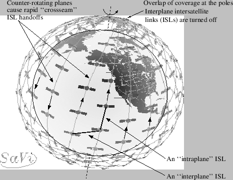
Figure 17.1:
Example of a polar-orbiting LEO constellation. This figure
was generated using the SaVi software package from the geometry center at the
University of Minnesota.
|
|
Polar orbiting satellite systems, such as Iridium and the proposed Teledesic
system, can
be modelled in ns. In particular, the simulator supports the specification
of satellites that orbit in purely circular planes, for which the neighboring
planes are co-rotating.
There are other non-geostationary constellation configurations
possible (e.g., Walker constellations)- the interested user may develop new
constellation classes to simulate these other constellation types. In
particular, this would mainly require defining new intersatellite link
handoff procedures.
The following are the parameters of satellite constellations that can currently
be simulated:
- Basic constellation definition Includes satellite altitude,
number of satellites, number of planes, number of satellites per plane.
- Orbits Orbit inclination can range continuously
from 0 to 180 degrees (inclination greater than 90 degrees corresponds to
retrograde orbits). Orbit eccentricity is not modeled. Nodal precession is
not modeled. Intersatellite spacing within a given plane is fixed. Relative
phasing between planes is fixed (although some systems may not control phasing
between planes).
- Intersatellite (ISL) links For polar orbiting
constellations,
intraplane, interplane, and crossseam ISLs can be defined. Intraplane ISLs
exist between satellites in the same plane and are never deactivated or
handed off. Interplane ISLs exist between satellites of neighboring
co-rotating planes. These links are deactivated near the poles (above
the ``ISL latitude threshold'' in the table) because the antenna pointing
mechanism cannot track these links in the polar regions. Like intraplane ISLs,
interplane ISLs are never handed off. Crossseam ISLs may exist in a
constellation between satellites in counter-rotating planes (where the
planes form a so-called ``seam'' in the topology). GEO ISLs can also be
defined for constellations of geostationary satellites.
- Ground to satellite (GSL) links Multiple terminals
can be connected to a single GSL satellite channel. GSL links for GEO
satellites are static, while GSL links for LEO channels are periodically
handed off as described below.
- Elevation mask The elevation angle above which a GSL
link can be operational. Currently, if the (LEO) satellite serving a terminal
drops below the elevation mask, the terminal searches for a new satellite
above the elevation mask. Satellite terminals check for handoff opportunities
according to a timeout interval specified by the user. Each terminal
initiates handoffs asynchronously; it would be possible also to define
a system in which each handoff occurs synchronously in the system.
The following table lists parameters used for example simulation scripts
of the Iridium17.1 and Teledesic17.2 systems.
Table 17.1:
Simulation parameters used for modeling a broadband version of
the Iridium system and the proposed 288-satellite Teledesic system.
Both systems are examples of polar orbiting constellations.
|
Iridium |
Teledesic |
| Altitude |
780 km |
1375 km |
| Planes |
6 |
12 |
| Satellites per plane |
11 |
24 |
| Inclination (deg) |
86.4 |
84.7 |
| Interplane separation (deg) |
31.6 |
15 |
| Seam separation (deg) |
22 |
15 |
| Elevation mask (deg) |
8.2 |
40 |
| Intraplane phasing |
yes |
yes |
| Interplane phasing |
yes |
no |
| ISLs per satellite |
4 |
8 |
| ISL bandwidth |
25 Mb/s |
155 Mb/s |
| Up/downlink bandwidth |
1.5 Mb/s |
1.5 Mb/s |
| Cross-seam ISLs |
no |
yes |
| ISL latitude threshold (deg) |
60 |
60 |
|
Tom Henderson
2011-11-05
